Our Wedge Barriers Diaries
The 5-Second Trick For Wedge Barriers
Table of ContentsSome Known Details About Wedge Barriers Not known Incorrect Statements About Wedge Barriers
How Wedge Barriers can Save You Time, Stress, and Money.
g., springtime assistance 65 )may be dealt with to the end of the spring pole 58 to allow compression of the springs 60. As the springs 60 are pressed between the springtime sustains 62, the spring setting up 54 generates a pressure acting on the webcam paired to the spring pole 58 in a direction 66. The remaining pressure used to
the cam webcam deploy release wedge plate 16 may be provided supplied an electromechanical actuator 84 or other various other. The springtime setting up 54 and the actuator 84(e. g., electromechanical actuator)may run with each other to translate the camera and raise the wedge plate 16.
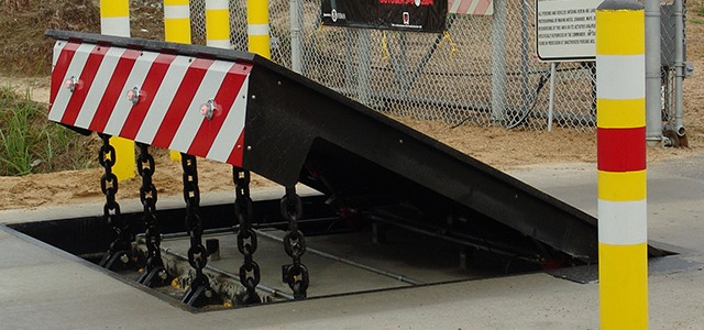
As stated above, the springtime setting up 54 exerts a constant pressure on the cam, while the electromechanical actuator might be controlled to apply a variable pressure on the webcam, consequently enabling the training and decreasing( i. e., releasing and withdrawing )of the wedge plate 16. In certain embodiments, the constant pressure used by the spring assembly 54 might be flexible. g., electromechanical actuator) is impaired. As will certainly be valued, the springtime setting up 54 may be covered and safeguarded from debris or other aspects by a cover plate(e. g., cover plate 68 received FIG. 4) that may be significantly flush with the raised surface 38 of the foundation 14. As pointed out above, in the deployed position, the wedge plate 16 serves to block gain access to or travel beyond the barrier 10. For example, the barrier 10(e. g., the wedge plate 16 )may block pedestrians or lorries from accessing a property or path. As discussed over, the obstacle 10 is connected to the anchor 30 secured within the structure 14,
front brackets 71. Consequently, the link settings up 72 might pivot and revolve to enable the collapse and extension of the link settings up 72 throughout retraction and release of the bather 10. The linkage assemblies 72 cause motion of the wedge plate 16 to be limited. For instance, if a lorry is taking a trip in the direction of the deployed wedge plate 16(e. For instance, in one situation, the security legs 86 might be prolonged throughoutmaintenance of the obstacle 10. When the safety legs 86 are deployed, the security legs 86 support the weight of the dig this wedge plate 16 versus the surface area 12. Because of this, the training mechanism 50 may be deactivated, serviced, removed, replaced, etc. FIG. 5 is partial perspective sight of a personification of the surface-mounted wedge-style barrier 10, showing the webcam 80 and the webcam surface areas 82 of the training mechanism 50. Particularly, two camera surfaces 82, which are referred to as reduced web cam surface areas 83, are placed listed below the webcam 80. The reduced camera surface areas 83 might be dealt with to the surface 12 (e. As an example, the reduced cam surfaces 83 and the placing plate 85 might develop a single piece that is protected to the anchor 30 by bolts or other mechanical bolts. Additionally, 2 cam surface areas 82, which are described as upper cam surfaces 87, are positioned over the web cam 80 and combined to (e. In other personifications, intervening layers or plates may be positioned between the surface area 12 and the reduced camera surfaces 83 and/or the wedge plate 16 and the upper web cam surfaces 87 As discussed over, the camera
80 translates along the web cam surface areas 82 when the wedge plate 16 is raised from the retracted position to the released setting. In addition, as mentioned above, the spring assembly 54 (see FIG. 3 )might supply a force acting on the camera 80 in the instructions 102 through spring rod 58, which might reduce the pressure the electromechanical actuator 84 is required to use to the webcam 80 in order to actuate and raise the wedge plate 16. 1 )to the released setting(see FIG. 4). As revealed, the webcam 80 includes track wheels 104(e. g., rollers), which call and translate along the webcam surface areas 82 throughout operation.